A growing number of organizations that produce mission-essential, safety-critical systems are using model-based systems engineering (MBSE) methods to ensure that the systems being delivered satisfy their intended requirements. The International Council on Systems Engineering (INCOSE), in its software engineering body of knowledge (INCOSE SE Vision 2020 [INCOSE-TP-2004-004-02], Sept 20), defines model-based systems engineering as follows:
Model-based systems engineering (MBSE) is the formalized application of modeling to support system requirements, design, analysis, verification, and validation activities beginning in the conceptual design phase and continuing throughout development and later lifecycle phases.
To maintain the veracity of the designs through the many phases in an industrial-development process, the system-development artifacts are expressed using formalized languages, such as the Systems Modeling Language (SysML) or the Architecture Analysis and Design Language (AADL). As development progresses from early requirements through the architecture and detailed-design phases, the models are transformed as knowledge is gained and constraints clarified. The transformation must preserve the validity of the model.
In this blog post, we will answer the following questions:
- What do we mean by a “modeling language”?
- Why use a modeling language, and what is the benefit?
- What practices exist to support modeling in general or specific to a particular language?
- What do tools support?
- If I’m using SysML already to define my system, why do I need AADL?
- What capabilities does AADL deliver that are not in SysML?
A Brief Example
Most of us who collaborate on multi-vendor large-scale system-development projects have encountered the delays caused by miscommunications and misunderstandings early in the project. These problems often result in mismatches that become apparent only much later in the project. For example, the Airbus 380 development project had significant delays in integrating components because portions of the fuselage were shipped to the integration facility with installed wiring that was the incorrect length. The pieces were manufactured by different organizations in different companies and had a miscommunication due to incompatibilities among MBSE tools. Issues identified early in the project were not fully addressed until they became entangled in the larger system context.
The delays that software engineers encounter when attempting to integrate modules developed by independent teams may not be as lengthy or as expensive as those experienced in the Airbus 380 incident. However, they can still be significant sources of embarrassment and cost overruns. The Architecture Centric Virtual Integration Process (ACVIP) provides a means to mitigate some of these kinds of overruns.
Let’s consider the example shown in Figure A. Three modules are being designed to form a graphics pipeline for rendering radar signals on cockpit displays. Each module transforms the data it receives and passes it along to the next module or the display (in the case of the last module). Each module is being implemented by a separate vendor based on expertise. The time required for data to pass through the pipeline is a driving requirement. The data must be processed and delivered to the screen in time to avoid any refresh flicker.
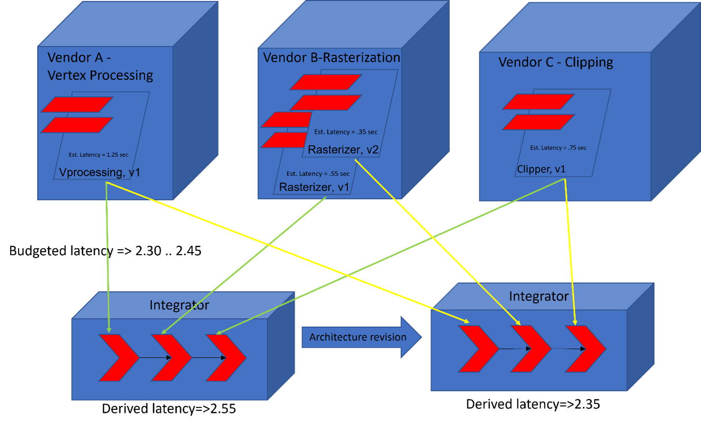
Figure A: A Scenario
Early in the project, when none of the modules have been implemented, the integrator’s system architect assigns a latency budget for each module in the pipeline, which is provided to the appropriate vendor as a requirement. As each module is decomposed, the module’s latency budget is decomposed in parallel to elements providing the functionality. Hardware and software engineers begin to predict actual latencies based on the designs and technologies defined in the early stages of development. Under ACVIP, the integration team uses MBSE tools to virtually integrate the modules and to predict the total latency in the pipeline. The predicted values are compared to the required values to identify places where the requirements are likely not to be met. This information is then forwarded to the vendors. Designs are revised and predictions recomputed.
In theory this analysis is straightforward. In practice, however, trying to apply the appropriate analysis and communicate the results from multiple computational flows through the system and multiple changes to meet requirements is challenging. Moreover, this analysis must be repeated after each modification to the architecture being analyzed. To make these analyses feasible, the mechanics of applying an analysis must be automated.
MBSE processes use languages, such as AADL, to model the system under development. These languages provide the constructs to represent architecture attributes, such as latency and security. The toolset for each language, such as the Open Source Architectural Tool Environment (OSATE) for AADL, provides algorithms that compute system-level attribute values from the individual component-level attribute values predicted by the modeled system’s architecture. While this effort is correctly performed early in the project, it can greatly reduce the effort required later in the project after the system is implemented and the physical measurements are taken.
Consider the development process shown in Figure 1 using a conceptual level of SysML. SysML defines a basic set of diagram types, each with its own syntax and with its own role to play in describing the intended system from a specific viewpoint. SysML adopts some of the diagram types from Unified Modeling Language (UML), ignores some parts of UML, and defines a few additional diagram types. Several iterations through the development steps of the system are usually required to fully understand and capture a robust system description.
The SEI works with many organizations to develop complex systems. These systems are often partitioned into a set of increments. For a modeling language to be useful, it must support this incremental approach. In this blog post, we illustrate several important interactions the approach must support—those occurring between diagrams as in Figure 1 and between development groups and organizations, those that occur during and across the increments, and those that apply as models become implemented in software.
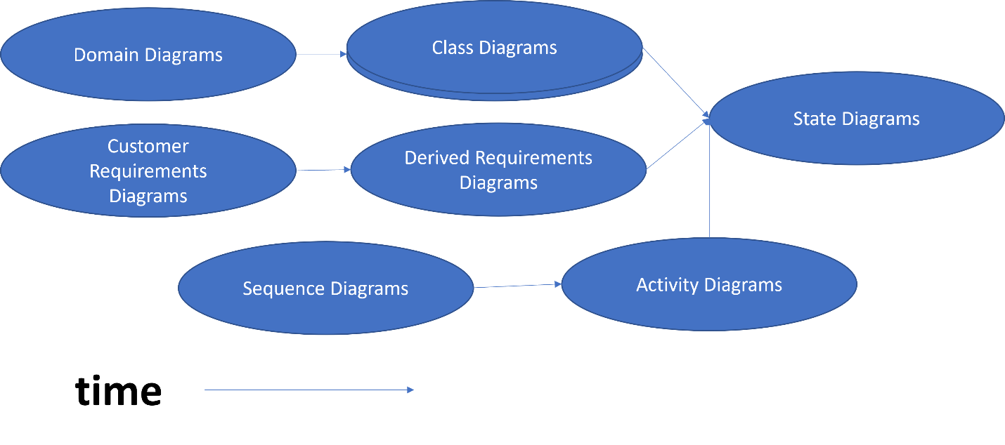
Figure 1: Modeling Sequence
Modeling Languages
A modeling language maps from the semantics of a system specification, represented in some natural language, to a logically consistent but somewhat abstract syntax. This approach allows complex systems to be represented in an easier-to-understand and more compact format at the expense of fidelity. As we show later, modern integrated development environments (IDEs) support the development of multiple models so that a single semantic related to software-system development can participate in mappings to multiple syntax formalisms, such as text and graphics. For example, the lack of fidelity in a SysML model can be compensated for by carrying along linkages back to some natural-language problem description.
Many languages have been used to build system models. We focus on the Object Management Group’s (OMG’S) SysML and SAE International’s AADL. Both are international standards, both have some degree of tool support, and both have been used in research-and-development projects in which the SEI has participated.
The two languages differ in terms of scope and depth. SysML derives from UML and adds support for more specific system concepts, such as computing hardware, system devices, data requirements, functional requirements, software, etc. It also has specialization and composition operators to facilitate the definition of almost any concept.
AADL likewise has general constructs that can be used to represent any system concept, but also has predefined constructs to represent system-level modeling concepts such as those for buses, processors, and more. AADL has syntax to support modeling of runtime details, such as nominal and error traces through the system. In general, SysML provides high-level, broad-stroke system models, whereas AADL is better suited for focused, detailed system and subsystem models, while still supporting high-level models for tradeoff analysis or other early lifecycle considerations. Having these explicit system concepts in the model supports requirements validation needed in the Department of Defense Architecture Framework (DoDAF) system and operation views.
SysML and AADL also differ in terms of tool support. While there are several open-source tools for SysML, the commercial tool CAMEO from NoMagic (Dassault Systemes) provides a full-featured commercial version that includes a number of extensions to the standard. The core of most AADL environment implementations is the Open Source Architectural Tool Environment (OSATE), which is an Eclipse-based IDE. The text-based syntax of AADL can be created and edited using any text editor, whereas the graphics-based syntax of SysML requires a compatible graphical editor.
Use Cases for Performing Modeling
Why do we use a modeling language? There are several use cases for applying a modeling language:
- The system engineer applies the modeling language to describe multiple system views in a less ambiguous, more succinct presentation than using free-form text and graphics.
- The system engineer uses a tool to support graphical representation of the system views.
- The system architect applies a tool to perform a quantitative analysis using system attributes that are part of a model representation.
To support these use cases, modeling languages provide a constrained vocabulary and graphical syntax for describing significant system structures and behaviors. The languages may also include attributes attached to specific structures of behaviors that can be used in analysis.
For SysML, the constraints are defined in a diagram that is an instance of one of the nine diagram types: block, inter-block, sequence, activity, state, requirements, parametric, use case, and package. This vocabulary defines the meaning of diagram-specific elements and graphics in each diagram. MBSE provides a modeler using SysML with guidance in which diagram to use to represent specific system features—structure, behavior, activity flow, data definition, etc., or more constrained vocabularies, which map onto a semantic and graphical syntax for describing significant system views or concerns.
AADL contains a set of modeling constructs and vocabulary for representation purposes. The AADL standard defines a text-based modeling language, which includes the ability to define commonly recognized structures and relationships, such as the operating-system processes and the threads and subprograms defined within the process. These structures can be annotated with property values that can be used to analyze system behaviors.
Tool support for AADL, in the form of the OSATE, adds a specific graphical notation and model-editing capabilities. The text and graphic views to the model under manipulation are kept in synch so that each engineer can consider the model from their preferred perspective. Creating an instantiation of the model is fast, and a simulated execution of the model provides the basis for evaluating runtime attributes.
In addition to graphical or textual modeling to document the engineering concerns of a system, modeling languages must include property descriptions to support analysis of the model. The analysis may be limited to syntax checking, e.g., a diagram has an illegal connection between elements or a text block references undefined identifiers or elements. A more comprehensive analysis might compare architecture requirements to the property descriptions in the model to determine if the requirements are to look at timing, resource utilization, or safety and hazard analysis.
The tool support for the language can provide the modeling capability and deliver analysis reports. Both CAMEO for SysML and OSATE for AADL can provide these analyses. AADL with OSATE has the advantage of built-in analysis based on language constructs that define properties, ranges of actual values, and well-tested algorithms that can “walk the model” to collect property values. For SysML, the tool environment is not as well populated with analytic features since SysML analytic tools are limited to what the modeler can create with available resources.
Modeling and Virtual Integration
We can state a fourth use case as follows:
4. A user applies a modeling language to define individual models that can be integrated and analyzed to reflect total system properties.
MBSE in general can support this use case. The Architecture Centric Virtual Integration Process (ACVIP) explicitly supports the use case through OSATE and AADL. It extends the usual MBSE product-development definition to include an analysis activity as the architecture elements are realized and integrated. In addition, properties within individual elements can be integrated to form whole system properties for end-to-end analysis. This capability, built into the OSATE toolset, supports users in representing and reasoning about product attributes, such as behavioral latency.
The virtual-integration aspect of ACVIP allows model elements from various sources to be integrated, according to a pre-agreed architecture, into a system model. Attributes are defined on the constructs in these elements and used by algorithms in OSATE to compute specific metrics such as latency for a specific path through the model. SysML models could be used for this purpose, but each user or user group must define their SysML modeling approach to guarantee end-to-end consistency of analysis results.
Architectures are evaluated and compared, with comparisons made to expected limits, using attribute values either directly measured in the actual running system late in the development process or computed by analysis algorithms. ACVIP analyses are defined to answer several different questions. Each analysis can operate at different levels of fidelity starting from estimates in the early stages of requirements gathering to analyses that precisely measure values late in development.
OSATE provides several predefined analyses for various attributes, including weight, power requirements, timing and scheduling, or error conditions. By computing the same attribute levels on a set of possible architectures or design decisions within an architecture, architecture decisions can be more objective. AADL has the infrastructure to facilitate this approach out of the box, whereas a SysML model must start from the basic modeling foundation and define a modeling strategy for analysis based on the mechanisms available in the tool environment and the constraints to which the models must conform.
These types of analyses are made possible by defining attributes on the elements in the model. Model constraints may be derived as early in the lifecycle as the problem-specification stage to estimate, for example, the overall timeframe for delivery of information between computing elements. As architecture and detailed designs mature in fidelity, the estimates become more accurate. During implementation and integration activities, these timing properties are compared to actual physical results to predict whether budgeted processing time is being consumed and must be increased or cannot be sustained within a given design.
For example, the reasoning occurring in a hazard analysis ranges from identifying potential hazards to recognizing a point failure and then making the necessary corrections. The modeler must not try to increase model fidelity too early and establish as fact vague ideas that have not been sufficiently matured. The modeler does have to reach a level of fidelity that is appropriate to the maturity of the model to ensure that the model can support the expected level of reasoning.
Multi-Language Modeling
A fifth use case states
5. The software architect translates a portion of an architecture, where the analysis that is required is not supported by the current environment, to a design environment where the analysis is defined.
Each modeling language has its own strengths and weaknesses. In some cases, it is advantageous to establish a workflow in which, with each development iteration, sections of the product model are analyzed by translating them into another language. Two recent examples include the translation of SysML models and Future Airborne Capability Environment (FACE) specifications into AADL models, which are then analyzed using the tools available in the OSATE toolset.
There are a few issues to consider:
- How much extra modeling is required to prepare for the translation? Translators are often used for the translation, but the source model usually requires some form of annotation, which would not be needed if there were no translation, to guide the translator. In the case of the SysML-to-AADL translator from Adventium, each SysML model element that requires translation must have a stereotype from the SysML-to-AADL library.
- How are fixes to defects, which are found in the analyzed submodel, propagated back into the full product model? The usual method is a manual edit of the source model based on the changes made to the target during analysis.
- How much knowledge is needed of two languages and two development environments? The bigger the sample taken from the source to be analyzed, the more of the target language and tooling the analyst will need to understand.
- What level of churn is introduced by having the two languages? The largest source of churn is a change to the modeling languages used to create either the source model or the target model. Changes in the source language will require changes to the tools needed to translate from source to target and maybe to the analysis tools in the target environment as well. Since both AADL and SysML are international standards currently in use, the rate of change will be much slower than for a newly designated language.
Comparison of Modeling Languages
In addition to SysML and AADL, Table 1 lists two other commonality or variability languages: FACE data modeling and features-based, which represent commonality and variability languages. The table does not provide sufficient information for a choice among make, buy, or mine (extract usable assets from existing artifacts). It is intended to summarize the features of interest in each of several different types of deployment.
|
SysML |
FACE |
AADL |
c/v |
|
|---|---|---|---|---|
|
target |
general |
aviation |
real-time |
domain |
|
purpose |
model |
model |
analysis |
identification |
|
limitations |
limited |
limited |
Certain |
limited |
|
issues |
major |
steep |
major |
decomposition |
We include FACE here as an example of a domain-specific language (DSL). A number of professional organizations and domain-focused industry consortia are producing DSLs or similar information based on the FACE data model. The FACE consortium, part of The Open Group, has stimulated the development of numerous assets for use in an MBSE environment. The FACE data-modeling language provides the beginnings of a DSL that is being used in many aviation software-development projects. The language is expressive but limited to the aviation domain. It expresses agreed-upon mental models in the target.
The c/v column in Table 1 refers to a specific class of DSL formed from the constructs from the commonality and variability analysis of a specific domain. These constructs are built by derivation from SysML or AADL basic constructs. They may eventually be the subject of Java annotations. This approach allows for a more natural modeling environment for systems engineers who are more familiar with the problem domain than the solution domain.
The scope of a features-based language is more narrow than that of languages such as FACE. The feature approach gathers constructs from a set of systems within a defined product ecosystem while the FACE approach draws from the more loose association of some organization populated by collaborating competitors.
The choice of modeling language is largely tool-driven since most languages have sufficient expressiveness. The development team can take advantage of the domain-specific origins of the DSL by being certain that keywords in the language are understood by the language users. This capability is particularly important in Agile development environments where separate documentation is limited and having a readable model is necessary.
Choosing the modeling language has broader implications than is initially obvious. In most cases, the model-evaluation toolset is actually separate from the definition of the modeling-language-manipulation toolset. What usually happens is that a tool chain is defined that ties together tools for editing models and tools for evaluating models. The OSATE is an example of this design. OSATE contains a single representation of the artifact under analysis. Each analysis algorithm traverses this single representation saving the time and space to build multiple program representations. The model-evaluation portion of the IDE will usually change faster than the language portion, particularly if the language is standardized. This difference in the rate of change results in a plugin architecture supporting the tools being extended by outside parties.
MBSE in a Product Line Context
To illustrate the concepts presented in this post, we consider use of MBSE in a product line development effort using the five use cases listed above. We focus on the product line concepts of commonality/variability, inheritance relationships, and strategic reuse. We further assume that SysML is being used to model the basic set of core assets in the product line and that AADL is used to provide analysis capability.
- Use cases 1, 2, and 3 address using modeling languages to present the important system details accurately. In a product line, there are several important views. (1) There will be relationships among the multiple product specifications based on common or specialized features. The relationships may include specialization among products (high-capacity products are derived from standard-capacity products), and there may be constraints among product parts and parts (product alpha is specified to handle top-secret material, so components that are not rated top secret cannot be composed into product alpha.) (2) There are relationships among the various component definitions, creating families of component types and subtypes based on inheritance relationships. (3) The flows of commands and data through the system are represented by the interface connections among components. Each of these relationships are typically the source of system views in the architecture model.
- Use case 4 addresses the need to integrate product parts that are developed at different times and/or by different organizations and have different implementations providing compatible behavior. (1) The guarantee of interchangeability comes from interface descriptions that are completely specified with respect to the scope of the interface, structured consistently with the structures and behavior defined on both sides of the interface, and that correctly specify the interface with respect to the intent of the product line. (2) The guarantee of compatible behavior comes from providing an accurate implementation of the behavior specified for the interface using a modeling language with strong type checking and robust semantics.
- Use case 5 addresses the need to translate information from one modeling language to another to take advantage of analysis capabilities available in a language other than the initial language. For example, in a product line there is often the opportunity to (1) apply the same analysis to similar product artifacts, and (2) repeat an analysis after every modification of a portion of the maturing design; for example, if the latency of a particular use case is critical. Particularly establishing an automatic translation from one language that does not provide latency analysis to another that does provide that analysis may be worth the effort.
Future Evolution of SysML, AADL, and MBSE
Both SysML and AADL continue to evolve, with new versions of the languages and supporting tool environments. The next major revision of SysML is likely to add a text-based syntax to the current graphical and XMI-based syntax. The error-modeling annex in AADL is being more tightly integrated into the nominal flow modeling of the core language, thereby improving traceability through the model. These improvements in expressiveness are part of the maturation of the tools available to support MBSE.
The processes that shape MBSE continue to mature. Virtual-integration actions can be added to many different development processes to give an earlier warning of incompatibilities. MBSE is increasingly being expanded over the full development lifecycle, including automatic code generation directly from an evaluated model. These enhancements help eliminate common sources of error, such as translation errors.
The increase in complexity of many software systems, particularly mission- and safety-critical control systems, must be met by increasingly sophisticated development techniques. MBSE provides tools and processes to meet these challenges, but there is much work left to do. In particular, the demands placed on the architect continue to evolve as do the efforts to automate development. Languages such as Risk Analysis and Assessment Modeling Language (RAMML) make it possible to automatically reason about risks of various types. New annexes to AADL for areas such as cybersecurity also increase the scope of analyses possible.